

REQUEST A QUOTE
How can we help you with your metal finishing needs?
CUSTOMER AWARENESS REGARDING OUR RFQ PROCEDURE
Essential information mandated by NADCAP
Specifications for the electro-finishing industry, whether Military, Federal, ISO, ASTM or SAE-AMS specifications, have an initial section that contains essential information mandated by NADCAP to be supplied by the purchaser to the electroplater.
More times than not, much of this information is omitted from part prints and purchasing documents which opens the door to potential poor communication and finishing shortfalls.
Please take a moment to review these common ommision and ensue that you provide those to us when submitting your quote.
Plating Thickness and Tolerance Requirements
Often a minimum/maximum thickness tolerance without a defined checkpoint cannot be realistically obtained with a traditional electroplating process. For example, a plating specification that lists a minimum plating thickness of 0.0005” and a maximum plating thickness of 0.0008” for all surfaces of an electroplated part would not be achievable on most part geometries due to the inherent variations in electrolytic plating distribution.
Plating thickness varies due to the inconsistent distribution of plating current on an electroplated part. Ionic plating current, like electrical current, takes a path of least resistance with the corners and ends of a part receiving a higher current density and therefore higher plating thickness. If the design of a component requires a very tight plating tolerance, it is important to designate a functional surface where a plating thickness check point can be established. If the plating is specified as 0.0005” minimum and 0.0008” maximum with a specific checkpoint, a plating protocol can generally be developed to consistently meet this requirement. Any specific part dimensional tolerances should be addressed in combination with a plating thickness checkpoint to allow for a combined plating thickness and part dimensional inspection protocol.
Plating Build Up on Threads
It is not uncommon for improper allowance to be made for plating buildup on threads. Since plating builds on two sides of the part and both sides of the thread land, a total of four times the nominal plating thickness should be used as a guide for the increase (male) or decrease (female) in thread pitch.
The formula below details the calculation for change in pitch diameter as a function of the plating thickness and included angle
(Note: the included angle for most common thread forms is 60-degrees):
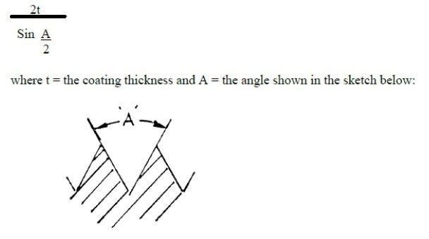
As an example, a 0.0002” plating thickness will cause the pitch diameter of a male thread to increase by a factor of four or 0.0008” for standard 60° UNC or UNF threads. This plating buildup is even further exaggerated on the lead threads of long fasteners or shafts where a localized plating thickness at the lead thread may be as high as four to five times the nominal thickness depending on where the plating thickness checkpoint is established. In such a case, the target plating thickness of 0.0002” may be as high as 0.0008” as measured at the lead thread resulting in as high as 0.0032” increase in thread pitch.
In such applications, it is very important to discuss allowances for thread pitch build and define a plating thickness checkpoint to ensure that parts can be successfully plated and meet post-plate gauging requirements.
Condition of the Incoming Material
 It is not uncommon for a metal finishing facility to receive parts with a heavy oil or heavy heat treat scale. This type of a condition is generally not discussed during the quoting stage nor are there advisories on part prints, specifications or purchasing documents. Excessive oil and heat treatment scale require additional operations to prepare the parts for successful finishing. The additional processes are often “off-line” in that they are a separate process independent from the plating line. Such processes include aggressive chemical descale processes. These steps add additional time/cost that are generally not included in a standard quote. In such cases, further discussion is required to determine the most cost effective way to prepare future orders of parts for plating. Often proper cleaning of parts prior to heat treatment, alternative heat treatment methods such as vacuum heat treating or cleaning prior to heat treatment can ensure parts are received at Mid-Atlantic Finishing ready-to-plate thereby eliminating additional preparatory steps & turnaround time.
Hardness or Strength Requirements
Racking Contact Location
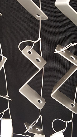 For parts that are rack plated, allowance must be made for contact locations of the rack tips. The rack tips are what physically contact the part to fixture it throughout the plating process. At the rack tip contact points there will nearly always be rack marks and lack of full plating coverage. This is due to the fact that current passes through the rack tips and into the part at the contact points.
In addition, plating chemistry/solutions cannot fully wet the surface of the part beneath the rack contact points. Due to the fact that the plating coverage will be incomplete with possible visible marks at the contact points. It is important that the purchaser convey non-functional or non-critical locations on the drawing where racking is permissible. This is usually a location where the purchaser deems that rack marks are not detrimental to the functionality nor physical appearance of the part.
Surface Roughness
REQUEST FOR QUOTE
Please use this form to Request a Quote on a project. For general inquiries, use our General Contact Form.